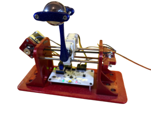
Inverted Pendulum
A fully 3D-printed inverted pendulum setup with custom electronics, featuring PID-based control implemented in C. A compiled GUI, developed in Rust, provides real-time communication and monitoring.
Control engineering, KiCad, C, Rust, Autodesk Fusion, 3D-printing
- Design a pendulum mounted on a cart. The pendulum must move freely, and sensors should be implemented to determine the position of the cart, including the pendulum's angle.
- A stepper motor is used to drive the cart's movement.
- To prevent uncontrolled movement beyond the cart's range, endstops should be implemented to stop the system safely.
- All sensor data should be read by a control system that also drives the stepper motor.
- Implement a cascade control strategy that keeps the pendulum upright while also steering the cart to the desired position.
- A user interface should allow the user to start and stop the system, and indicate its current status.
- All components should be capable of being 3D-printed and assembled in a basic workshop.
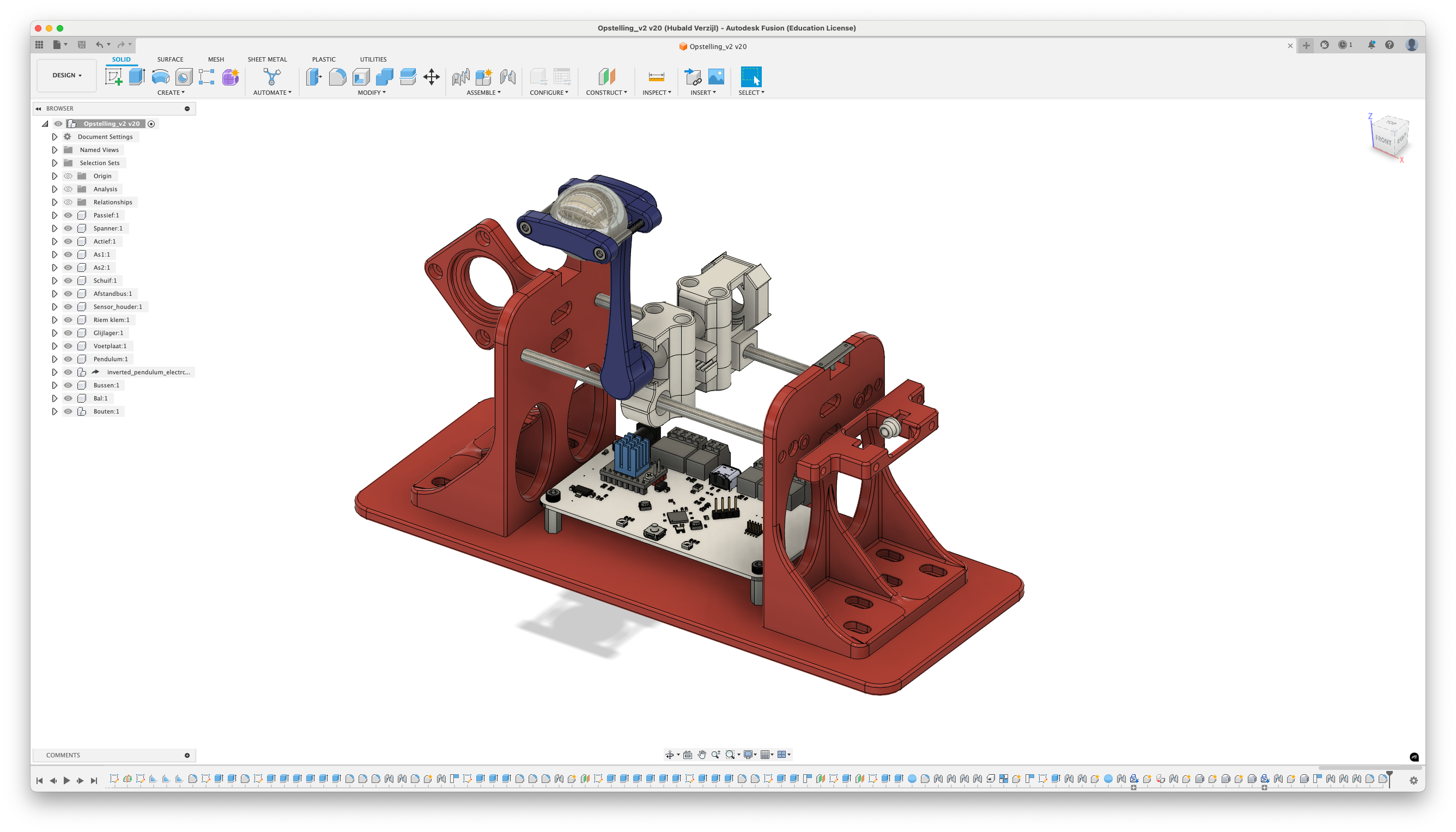
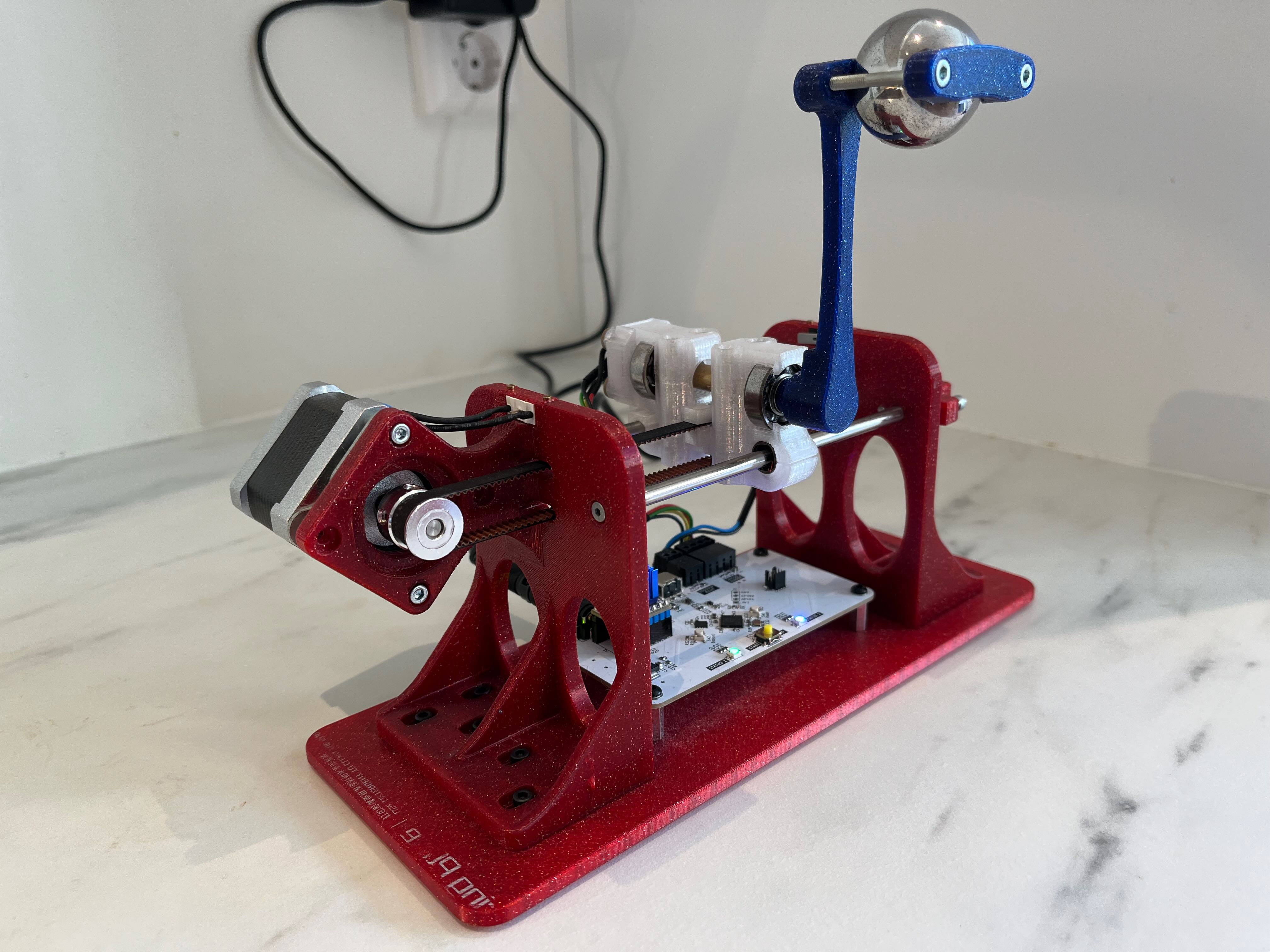
The hardware setup consists of several key components:
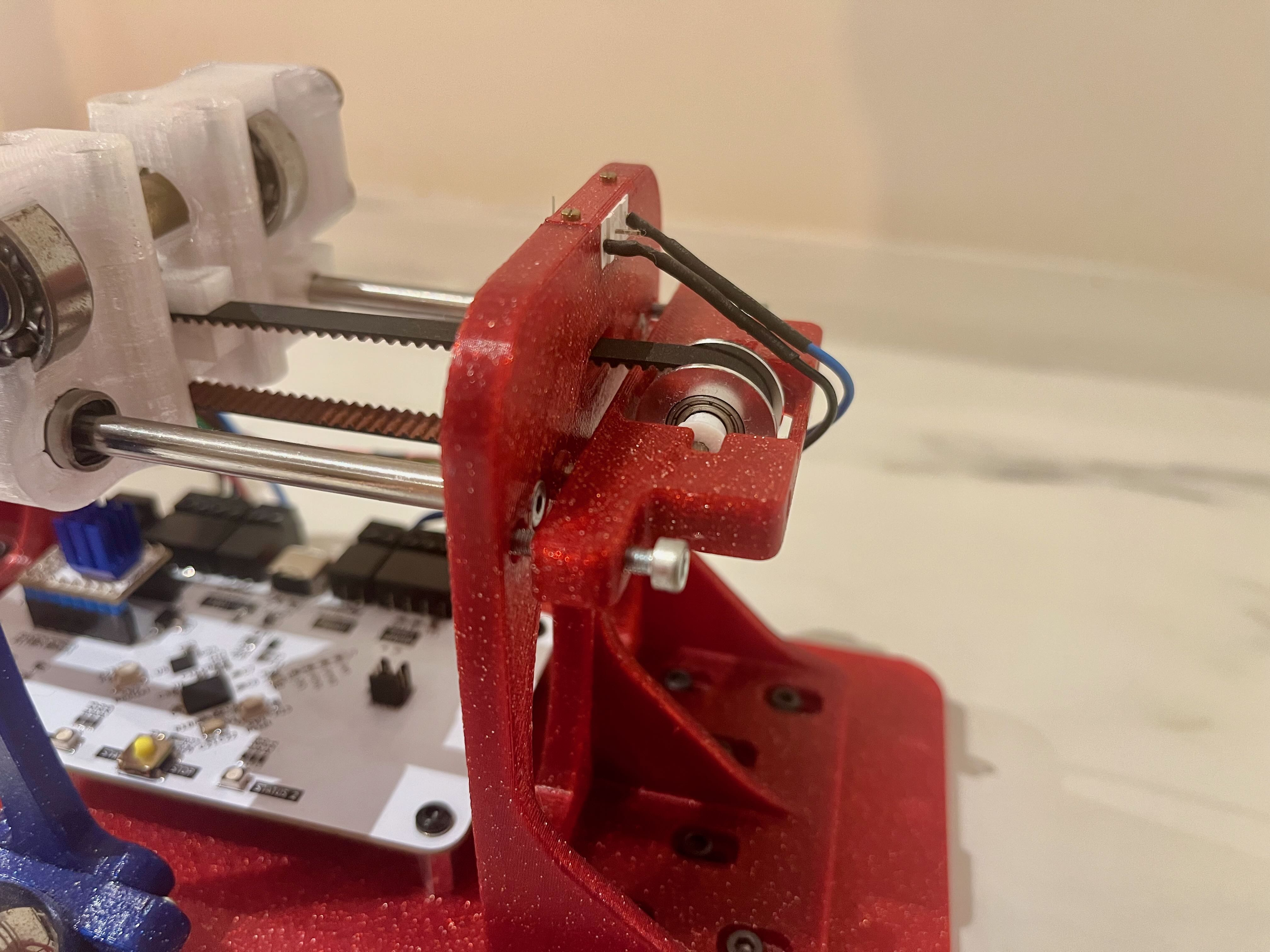
- Two 8 mm shafts that form a linear guide for the cart.
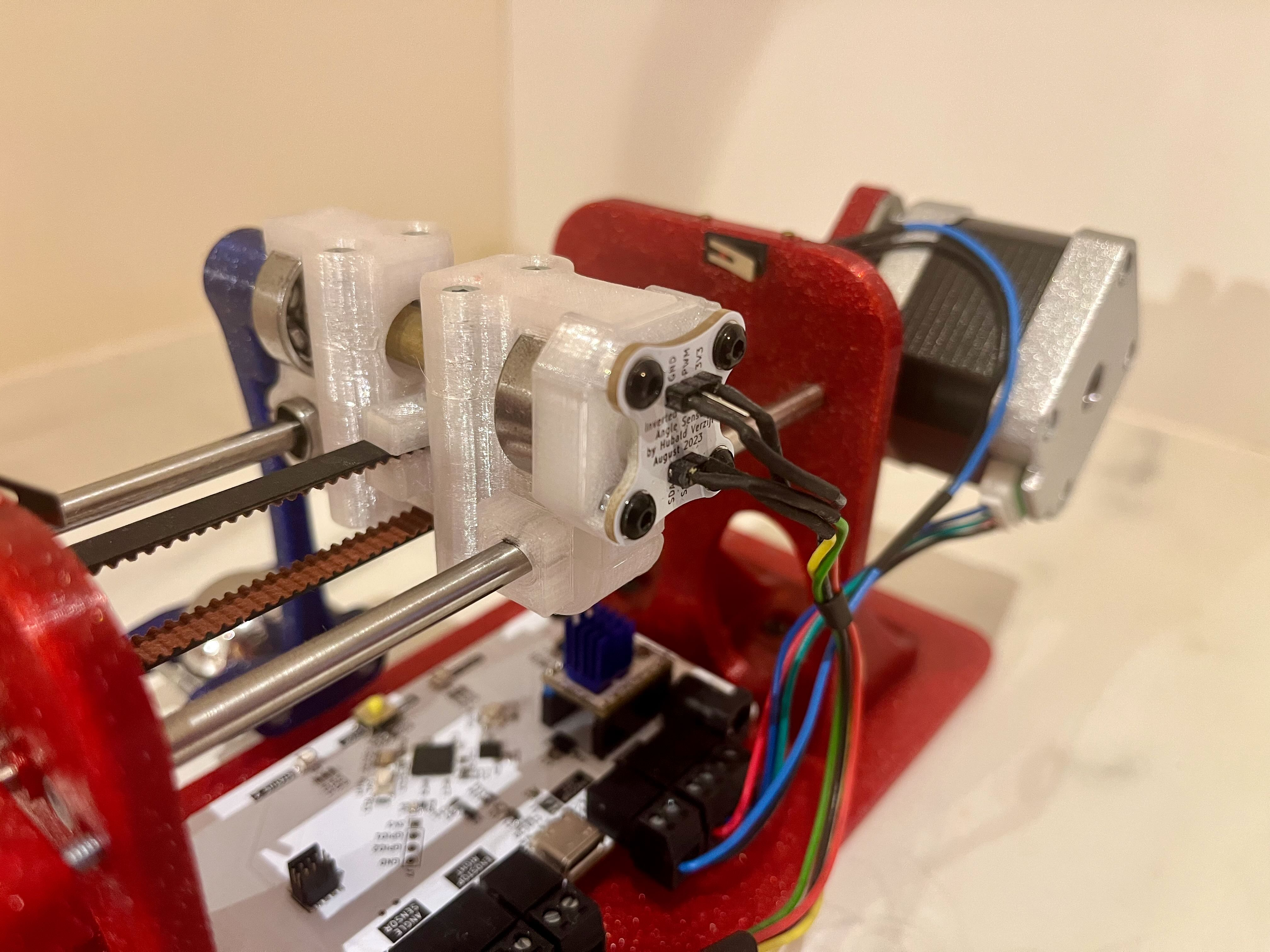
- A stepper motor to drive the cart's movement.
- A pendulum rod, mounted on the cart, that can swing freely.
- A magnet is placed on the pendulum rod, next to a rotary position sensor/encoder for angular measurements.
- A large metal ball is placed at the end of the pendulum rod to increase the inertia and make the system more sluggish. One could also state that the pendulum's bandwidth is reduced.
- Endstops to prevent movement beyond the cart's range.
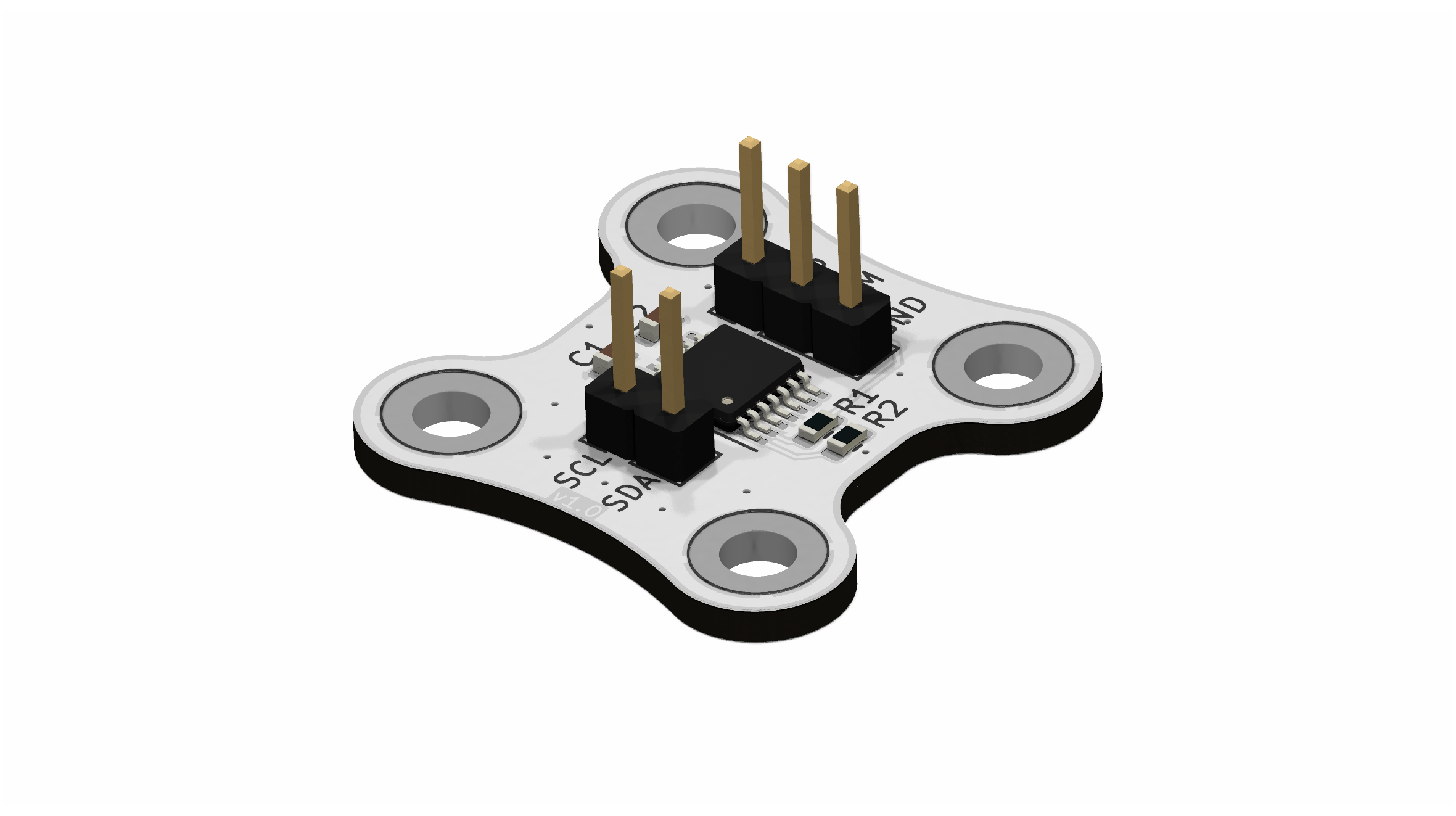
- Custom electronics for sensor readings and stepper motor control.
The two 8 mm shafts form a linear guide. To minimize friction and eliminate stick-slip behavior, linear ball bearings are used. The cart is driven by a stepper motor and connected via a rubber belt. A custom-designed tensioning part keeps the belt taut, reducing any backlash or dead space during movement. All components were designed in Autodesk Fusion and subsequently 3D-printed.
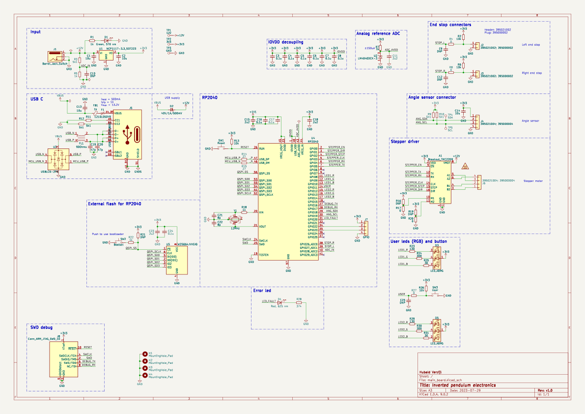
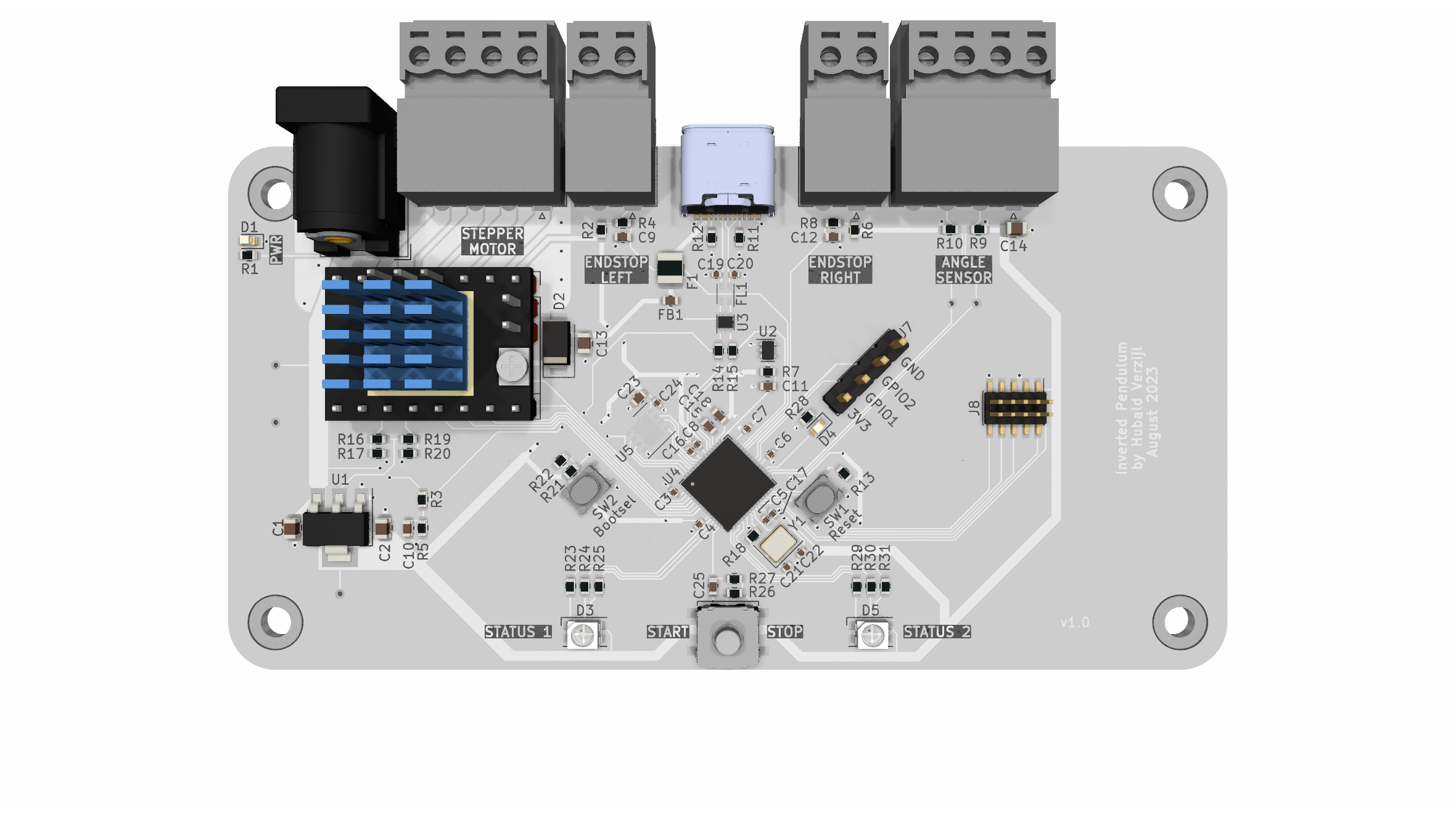
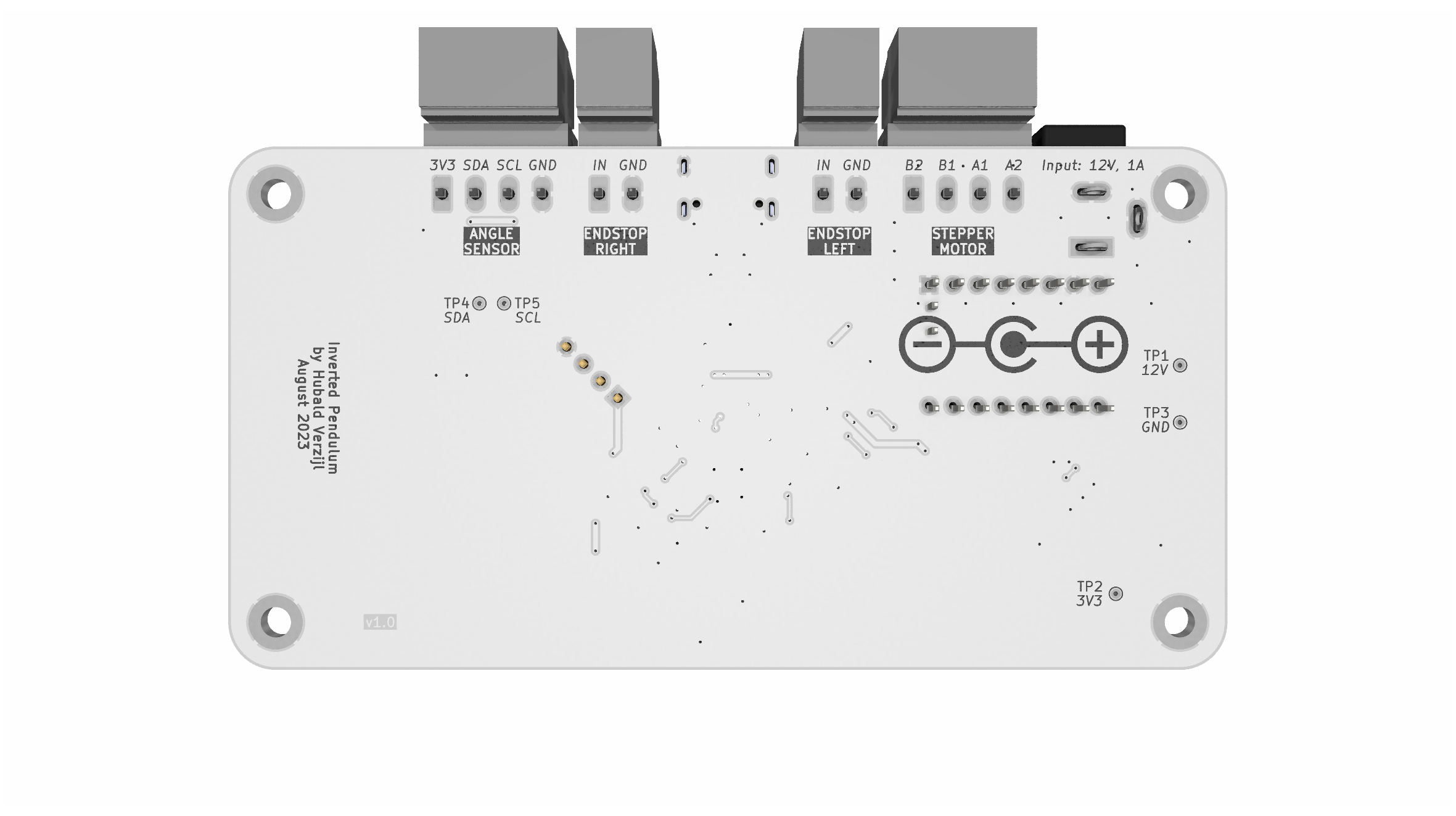
- 12V power input for supplying both the board and the stepper motor.
- NCP1117 voltage regulator providing 3.3V output.
- USB-C connector with USB 2.0 support and integrated ESD protection.
- RP2040 microcontroller with external flash memory and an SWD connector for programming.
- TMC2209 stepper motor driver.
- Connectors for endstops and an angle sensor (I2C interface).
- Two RGB LEDs and a user-programmable button.
The angle sensor board is based on a AS5048B: a 14-bit rotary position sensor. When a 2-pole magnet is rotated above the sensor, the digitized angles can be read via I2C.
The control strategy for the inverted pendulum is based on a cascade control system. The inner loop controls the angle of the pendulum, while the outer loop manages the position of the cart. The inner loop uses a PID controller to stabilize the pendulum at its upright position, while the outer loop adjusts the cart's position based on the pendulum's angle and desired position. To garanty stability, the inner loop should be much faster the the outer loop.
The inner loop is responsible for stabilizing the pendulum in its upright position. It employs a PID controller to regulate the chart's velocity based on the current angular error. The controller continuously calculates the difference between the desired angle (upright) and the actual angle, then adjusts the motor's speed to minimize this error.
Since it's challenging to define the exact equilibrium angle, the derivative of the angle (i.e., angular velocity) is used as a control reference and driven toward 0 rad/s. In equilibrium—whether the pendulum is upright or hanging downward—the angular velocity will be 0 rad/s.
The PID control law used is
\[ \dot{x}_{ang} = K_p e(t) + K_i \int e(t) \, dt + K_d \frac{de(t)}{dt}, \]
where the error term is defined as
\[ e(t) = \dot{\theta}_{ref} - \dot{\theta}, \]
and \( K_p \), \( K_i \), and \( K_d \) represent the proportional, integral, and derivative gains, respectively. Besides that, \( \dot{\theta}_{ref} = 0 \).
Without the outer loop, the pendulum may stabilize in an upright position, but without regard for the position of the cart. Ideally, the pendulum should remain upright at a specific desired location—typically the center or another reference point.
One of the challenges addressed by the outer loop is tracking a moving reference position. The system must ensure the cart settles around this target while keeping the pendulum balanced. To achieve this, a second PID controller is used, which computes the velocity command \( \dot{x}_{pos} \) based on the position error.
The position error is defined as
\[ e(t) = x_{ref} - x. \]
The total commanded cart velocity is given by
\[ \dot{x} = \dot{x}_{pos} + \dot{x}_{ang}. \]
Here, \( \dot{x}_{ang} \) is the output of the inner loop (responsible for balancing the pendulum), and \( \dot{x}_{pos} \) is the output of the outer loop (responsible for positioning the cart).
The embedded software is written in C using the Raspberry Pi Pico C/C++ SDK. The core task is to calculate the cart's velocity based on its position and the angular velocity of the pendulum. Several interrupts are configured to monitor the user button and the end stops, ensuring the system does not damage itself during operation. Since the microcontroller operates from a 5V USB supply, the RP2040's ADC is used to detect the presence of an external 12V power adapter. If the adapter is not connected, one of the user RGB LEDs turns red instead of green to indicate the absence of an external 12V power supply.
A stepper motor with a step size of 1.8° (requiring 200 full steps per revolution) is used to drive the cart. The TMC2209 stepper motor driver supports microstepping. By pulling both M1 and M2 to ground, the driver operates in 1/8 microstepping mode, resulting in 1600 microsteps per full revolution.
The motor driver controls the stepper motor by toggling the TMC2209’s STEP pin. Each toggle generates one microstep, causing the motor to move 1/1600th of a full revolution. The direction of rotation is determined by the state of the DIR pin. The system uses a GT2 timing drive pulley with a diameter of 12 mm, which results in a horizontal displacement of approximately 0.015 mm per microstep.
To achieve a specific cart speed, the STEP pin must be toggled at a corresponding frequency. To avoid timing conflicts and ensure that the frequency generation does not interfere with sensor measurements or introduce delays, the second core of the RP2040 MCU is utilized. A global variable is updated by the main core with the target frequency, and the second core reads this variable to control the STEP and DIR pins independently. This division of labor allows the primary core to focus on data acquisition and calculating the required cart velocity, while the secondary core handles motor control in real time.
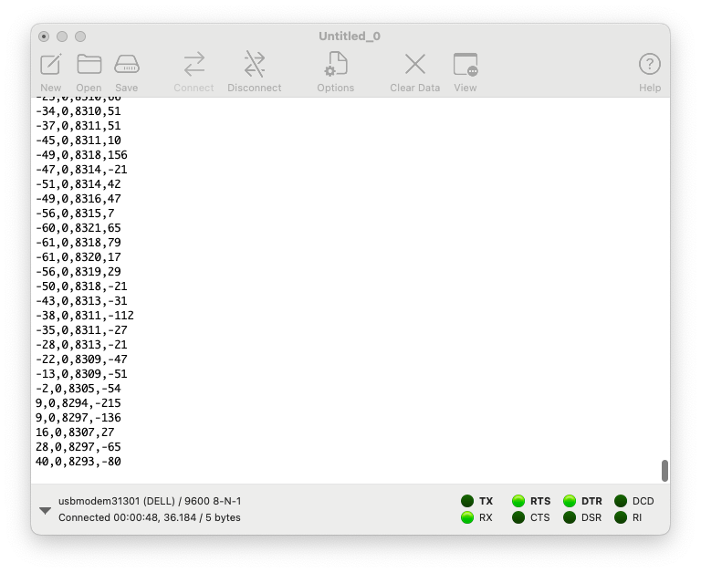
A virtual COM port is established over USB for communication with the host PC. It transmits data at 50 Hz, including the cart's position (in microsteps), the position setpoint, the pendulum angle (raw sensor value), and the angular velocity. It also receives the target position from the host PC. Serial port terminal applications like Coolterm can be used to display the incomming data.
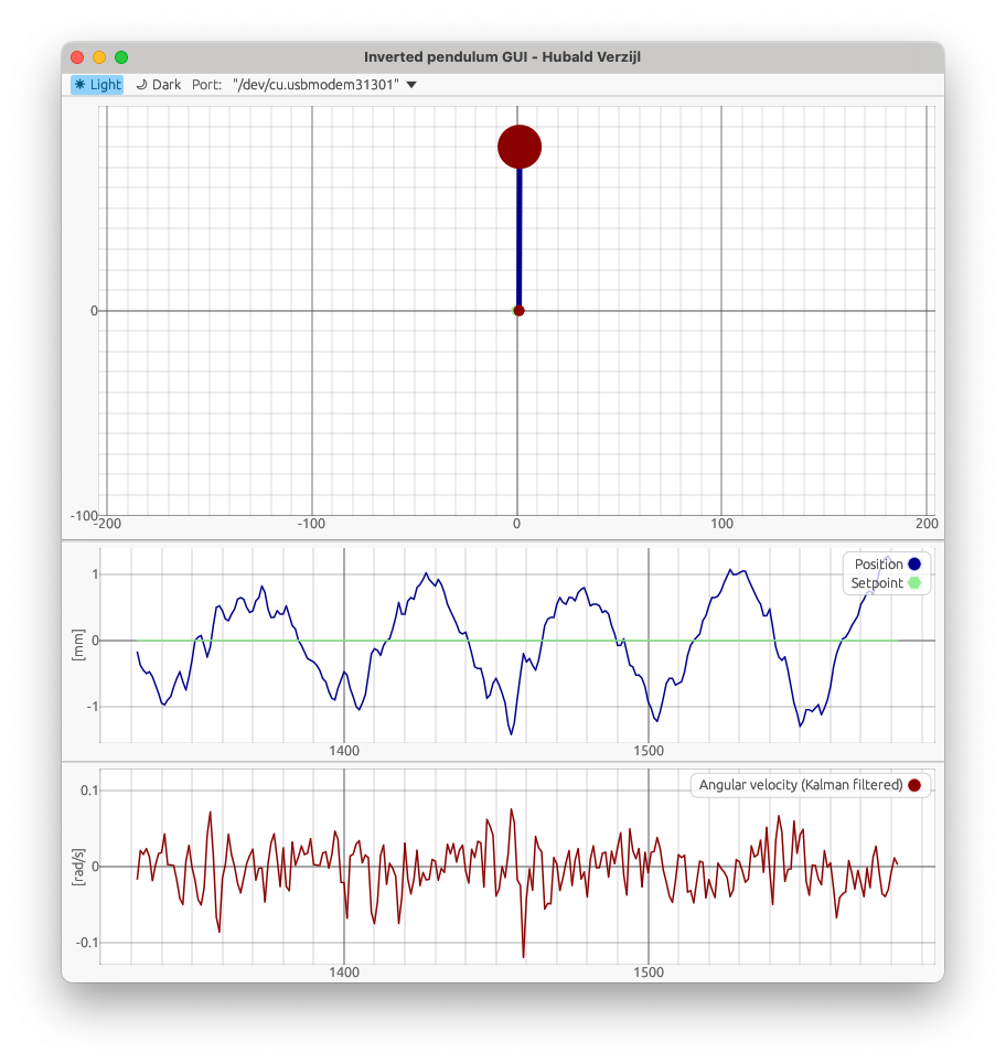
- Top: A visual representation of the cart (small red dot) and pendulum mass (large red ball). The user can click in this figure to update the cart's setpoint which is indicated by the green dot.
- Middle: Cart position vs. setpoint (blue and green lines).
- Bottom: Angular velocity of the pendulum, stabilized around 0 by the fast inner control loop.
This setup allows intuitive observation of both the slow outer loop (position control) and fast inner loop (pendulum stabilization) in real time.